
COVID-19 Prevention technology > UV Long Optical Path Sterilization System
REVOLUTIONARY AIR STERILIZATION SYSTEM WITH UV LIGHT
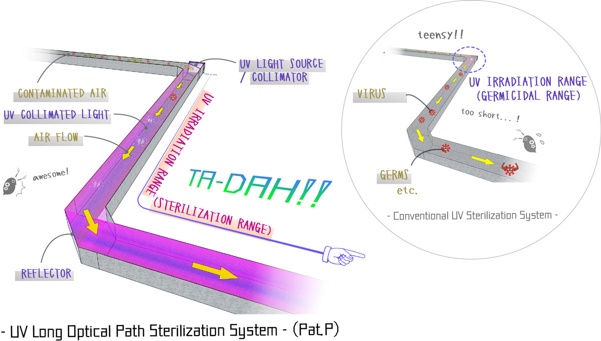
By converting ultraviolet rays into collimated light (parallel light) and matching the optical path of the collimated light with the duct, the air in the duct is continuously irradiated with the UV collimated light having high density energy and sterilized effectively and reliably. (Pat.P)
We believe the system may become an ultimate countermeasure aginst COVID-19.
SUMMARY
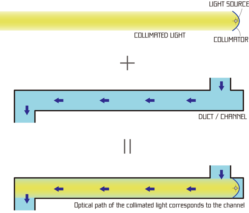
Converting germicidal UV ray into collimated beam with a collimater, such as a concave mirror, and corresponding the optical path of the collimated beam with the channnel for air flow can constitute a revolutioal air sterilization system.
Q. What is "collimated light?"
A. Collimated light (beam) is a bunch of parallel luminous flux (rays). It reaches very far.
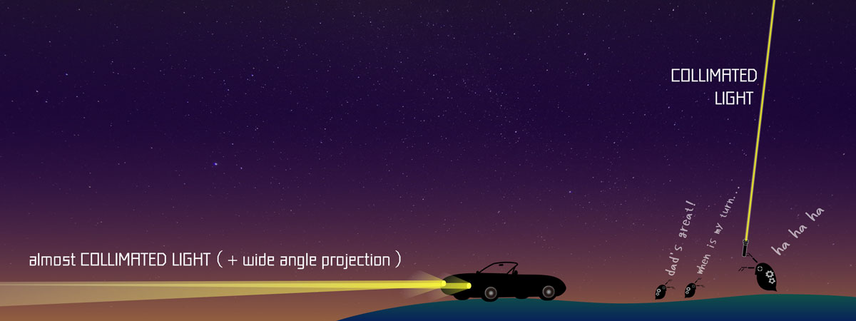
A collimated beam can reach far with little attenuation.
Setting a unit of a light and a collimator in the straight part of the duct...
...enables to irradiate inside the duct thoroughly even adopting a minimal UV lamp.
It means the air is countinuously irradiated with the ultraviolet rays for sterilizaton during the air passes through the straight part of the duct.
In conclusion, strong, effective and reliable (as designed) sterilization can be planned with the system.
Note) The parallelled beam is also called "collimated light"
The idea is expected to realize reliable and quite effective air sterilization system even using a small and weak UV lamp.
Also, it can constitute liquid sterilization system, as well.
Q: How to implement?
A: We have various ways of application. It can be installed in various locations.
You can configure an air sterilizer in the room, in the car, or in the airplane cabin. Not only constituting sterilization appliances, it can also be installed in existing air conditioning ducts and equipment, or incorporated into indoor structures.
Q: What is the significance and value in it?
A: It can be a solution to the situation where it is difficult to ensure required ventilation volume and vaccination alone cannot solve it.
As you know, most buildings and vehicles (except cars) do not have sufficient capacity of ventilation to prevent infection of COVID-19.
Even if a sufficient amount of ventilation is available, the air conditioning capacity cannot keep up.
We guess it has led to the capital cause of the serious expansion of infection in cold regions.
In addition, although vaccine development and vaccination preparations are underway, it is said that the vaccines alone cannot cope with the coronavirus, as it has multiple mutations and the immunity durations would not last long.
In fact, until now, humankind has not overcome even the less threatening colds and flu, and has developed and inoculated new vaccines every year.
For this reason, we believe that a mechanism that can effectively sterilize indoor air without depending on ventilation volume or air conditioning capacity would be a significant solution in preventing infection of COVID-19 and so on.
MECHANISM AND BASIC STRUCTURE
UV Long Optical Path Sterilization System realizes effective and reliable air sterilization by converting UV germicidal rays into a collimated beam with a collimator and matching the optical path of the collimated beam and the air duct.
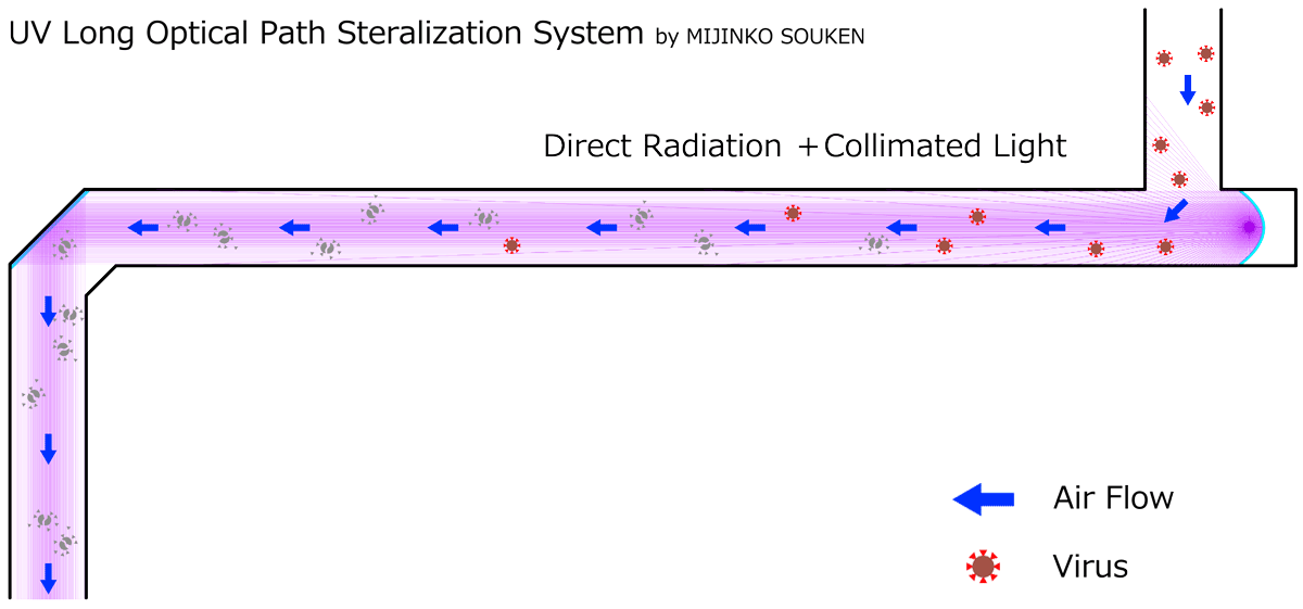
The air is continuously irradiated with high-density UV rays during passing the channel (duct) and sterilized effectively.
View details
PROBLEMS OF CONVENTIONAL UV STERILIZATION SYSTEMS - ATTENUATION OF UV RAYS
View
Sterilization capacity of the ultra violet irradiation can be estimated with following formula:
[density of permiating radiant flux (energy)] X [irradiation time]
Generally, sterilization with UV lamps is very common and verious devices are available, however, sterilization in this way is not enough effective/reliable because the flux (energy) density of the UV irradiation attenuates for the following reasons and most part of the UV energy has been abandoned without being used for sterilizatoin.
- Optical/geometrical reason
- Attenuation in permeation
- Attenuation in reflection
OPTICAL/GEOMETRICAL REASON
Density of UV luminous flux decreases in proportion to the distance from the light source for geometrical/optical reasons.
Radiant flux model varies as per the figure of the light source.
(Sorry, translation is underway...)
ENERGY AND THE UV LUMINOUS FLUX
visible rayの強さは、rayの物理的なenergyを、波長ごとに人の視覚に応じて重みづけされた、「光束」という物理量により表現されます。単位はlm(ルーメン)といいます。
光束は、人の視覚で捉えられる光のenergyを表現したものであり、実際の物理量の総量とは異なります。これに対し、UVなど、 visible ray以外のrayや電磁波の場合、「光束」ではなく、実際の物理量である、「radiant flux」という言葉で表現されます。
いずれにせよ、光束やradiant fluxという概念は、束状にモデル化されたray等によるenergyが、ある面を何本透過するか、というイメージで捉えられるよう、考えられたのでははないかと思います。
light sourceから放射されるradiant fluxは、幾何学的・opticalな理由から、light sourceのタイプにより、attenuationの度合いが異なってきます。
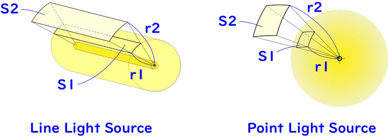
point light source
完全なpoint light sourceから放射されるradiant fluxは、3次元的に、各方向に対し均等に放射されます。point light sourceの周囲の、均等なradiant fluxdensity(energydensity)となる部分を結ぶと、球体面が形成されます。
うにではありません。
light sourceからの一定の立体角範囲に含まれるradiant flux(energy)の量は、light sourceからのdistanceに関わらず、一定となります。
line light source
line light sourceの場合、light sourceに直交する面上において2次元的に、各方向に対し均等に放射されます。light sourceの周囲の、均等なradiant fluxdensity(energydensity)となる部分を結ぶと、円柱面が形成されます。
radiant fluxは面状にモデル化すると理解しやすくなります。
light sourceに直交する面上において、light sourceからの一定の角範囲に含まれるradiant flux(energy)の量は、light sourceからのdistanceに関わらず、一定となります。
light sourceからの放射energydensity
上述のように、light sourceから一定の角度内は、light sourceからのdistanceに関わらず、radiant flux(energy)の量が一定となるため、下図のline light source・point light sourceそれぞれについて、light sourceからのdistanceがr1となる面およびr2となる面を通過するradiant flux(energy)R(J)は、等量となります。
逆にいうと、light sourceからのdistanceに対する、単位面積あたりのradiant flux(energy)、つまり、radiant fluxdensity(energydensity)は、以下のように考えられます。
※ここで、
r:light sourceからのdistance(m)、S:light sourceからのdistancerかつ一定の角範囲内となる円柱面上の面積(㎡)、Φ:light sourceからのdistancerの位置におけるradiant fluxdensity(J/㎡)、R:一定の角範囲のradiant flux(J)
とします。
line light source
r ∝ S
Φ = R/S
これらにより、
Φ ∝ 1/r つまり、radiant fluxdensityはlight sourceからのdistanceに反比例します。
例えば、図の場合、r2/r1=2であれば、S2/S1=2となり、light sourceからのdistancer1の面上に対し、distancer2の面上でのradiant fluxdensityは、1/2倍となります。
point light source
(rの2乗) ∝ S
Φ = R/S
これらにより、
Φ ∝ 1/(rの2乗) つまり、radiant fluxdensityはlight sourceからのdistanceの2乗に反比例します。
例えば、図の場合、r2/r1=2であれば、S2/S1=4となり、light sourceからのdistancer1の面上に対し、distancer2の面上でのradiant fluxdensityは、1/4倍となります。
つまり
light sourceからのdistanceが大きくなるほど、germicide能力が低下することがわかります。とりわけpoint light sourceの場合、顕著となります。
ATTENUATION IN PERMEATION
germicideに用いられるUVは、UV-Cと呼ばれる短波長領域のUVで、オゾンや酸素を透過すると、吸収されてattenuationします。
太陽rayにも含まれますが、大気中のオゾンや酸素に吸収されるため、地上には到達しません。しかしながら、UV-Cは生物のDNAを破壊するため、germicide作用と同時に人体にも有害であり、オゾン層破壊により地上に到達する危険性が指摘されています。
UV-Cは、他の波長領域のUVと比較して、透過によるattenuationが大きいものの、通常のairgermicidedevice内程度のoptical pathの長さでは、考慮する必要が無いものと考えます。
オゾンや酸素の他、air中を浮遊する埃や水蒸気、ウィルスを含む雑菌といったエアロゾルに衝突することによるattenuationも考えられますが、これは visible rayでも同様であり、通常の室内環境であれば、airが霞んで部屋の中が良く見えない、ということはないため、UV-Cの場合でも、ほとんど無視できるのではないかと考えます。
尚、長optical pathgermicidesystemは、水などの流体のgermicideにも用いることが可能ですが、水中は、air中と比較して、UVの透過率が非常に小さい(attenuationが大きい)ため、基本的に小規模なdeviceへのapplication(短distanceのoptical pathの形成)となります。
その他、UVを透過させる部材については、通常のガラスはUV透過率が低いため、石英ガラス等を用います。
ATTENUATION IN REFLECTION
UVは、通常の鏡ではほとんどreflectionしません。germicideに用いられる波長域のUVのreflection率は、一般に、アルミニウムで40~50%、ステンレスで20~30%程度となります。
通常、UVをreflectionさせる場合、アルミ蒸着による特殊なreflection面が用いられます。この場合、reflection率は80~90%程度に高めることもできます。UVgermicidedeviceは、light sourceの周囲の筐体内面をアルミ蒸着面とし、light sourceからのdirect radiationのみではなく、筐体内面でのreflection光を再利用するstructureとすることが一般的です。
筐体内面で10回reflectionした場合、optical pathのdistanceは、筐体内の内径の11倍となります。とはいえ、筐体内面を85%のreflection率の蒸着面としても、10回のreflectionでrayのenergyは20%以下に低下し、 long optical pathを計画しても、energyが低下しながらreflectionを繰り返しているため、当該optical path上のenergyの総和(germicideできるenergy)は限定的です。
さらに、筐体が閉鎖structureであれば、実際にはこれほど多くのreflection回数となるoptical pathを計画することは困難で、ほとんどのradiant flux(光束)をトレースすると、わずかなreflection回数ののち再びlight sourceをirradiationして、熱に変換されているのではないかと思います。
duct内にUVgermicidedeviceをinstallする場合は、通常のairgermicide器具と比較してlongなchannelに対してgermicidesystemをconstitutionすることとなりますが、アルミ蒸着等による内面のreflection面の処理は、コストが大きくなるため、light source付近の一定区間のみに限定されるものと考えられます。
UV Long Optical Path Sterilization Systemは、基本的に、collimator(放物面鏡)を用いてcollimated lightを生成するため、少なくとも一度reflectionすることとなり、その分、生成されたcollimated lightはattenuationします。
また、optical pathおよびchannelは、reflection板をinstallすることにより、屈折させることができます。reflection回数が多いほどUVrayはattenuationするため、optical pathおよびchannelは、極力屈折回数が少なくなるように計画します。
CONCLUSION
conventionalのUVgermicidedeviceは、上述の「...の課題」のように、UVrayのenergyやenergydensityのattenuationにより、effectiveなgermicideが困難でした。
これに対し、「UV Long Optical Path Sterilization System」は、UVをcollimated lightに変換することにより、通常の使用条件では半無限と言える長optical pathを実現し、革新的なgermicide effect の実現を期待することができます。
GENERATION OF COLLIMATED LIGHT WITH A COLLIMATOR
View
(Sorry, translation is underway...)
UVによるgermicide灯のlight source自体は、radiant fluxを放射状に放射しますが、collimator(放物面鏡)をinstallし、collimatorのfocal pointとなる位置に当該light sourceをinstallすることにより、放射状のradiant fluxは、collimated light(コリメート光)に変換することができます。
collimated lightは、一般に、遠くを照らすビームのようなまっすぐな光の出る懐中電灯(小学校のお泊りイベントで持参した人がヒーローだった、あの懐中電灯です)や、サーチライト、車のハイビームなどに用いられます。
UV Long Optical Path Sterilization Systemは、このcollimated lightとgermicide対象のairのchannelとを一致させることにより、airが当該channel上を通過する間中、継続的にgermicideされるように計画します。
※尚、長optical pathgermicidesystemに用いるcollimatorは、アルミ蒸着等による高いreflection率を持つreflection面とします。
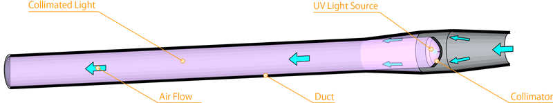
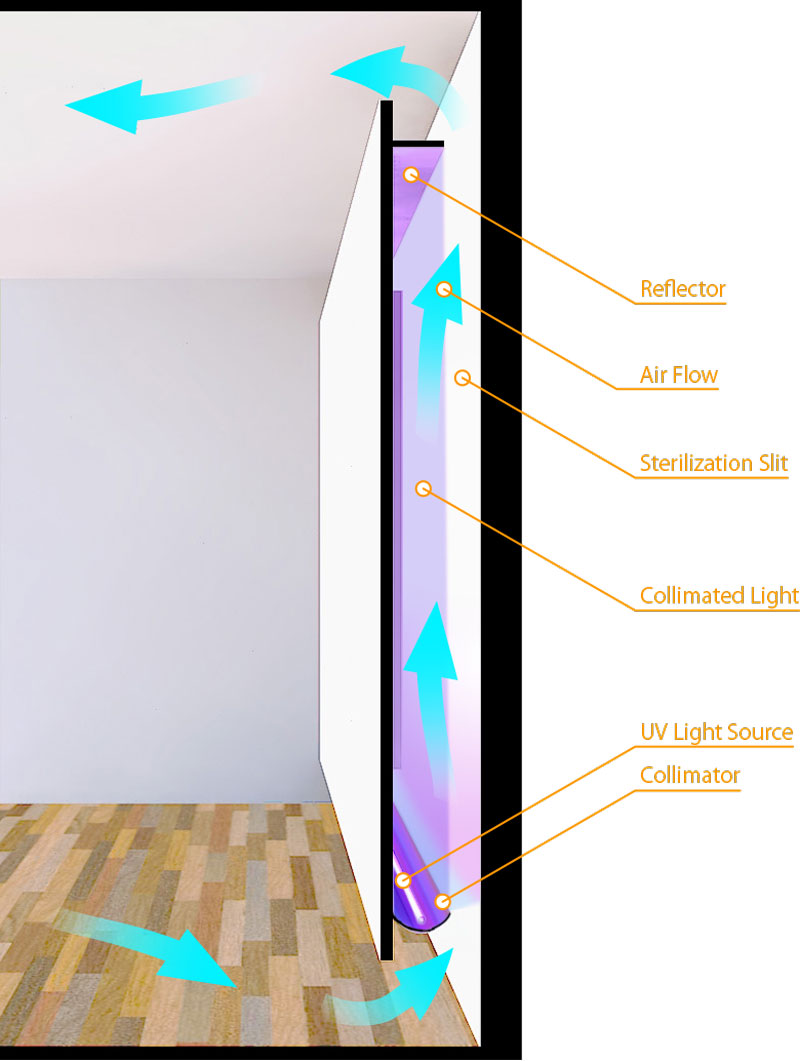
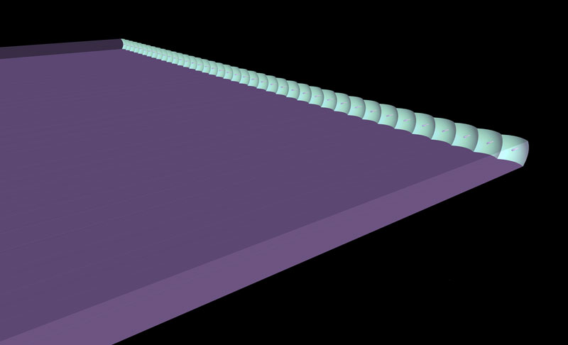
下の図は、air conditioningductに長optical pathgermicidesystemをconstitutionする場合の例として、collimator部分の拡大図を示しています。
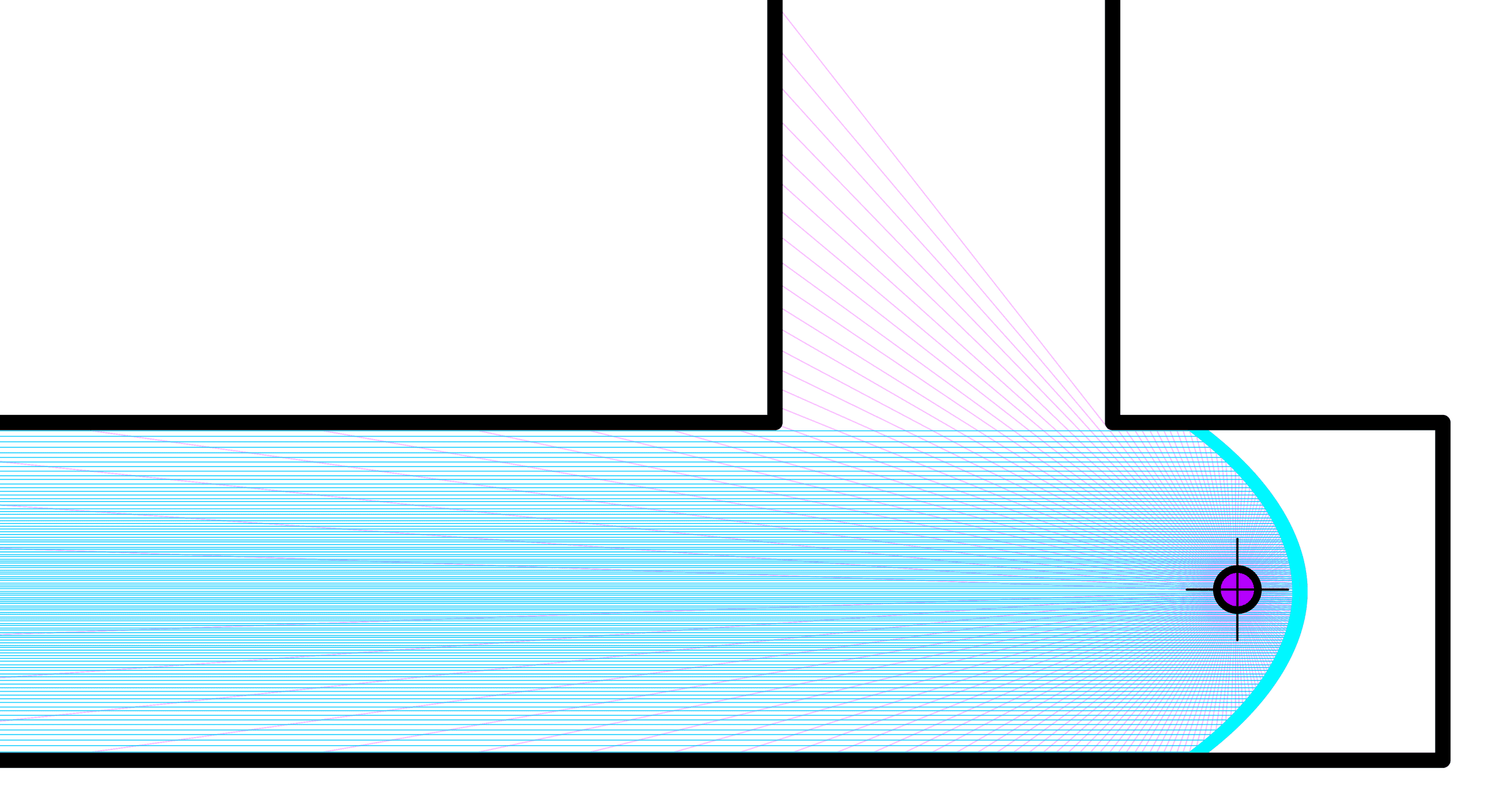
水色の曲面はcollimator、紫色の点はlight source、ピンク色の光束はdirect radiation、水色の光束はcollimatorでreflectionしたcollimated lightを表しています。
クリックして拡大すると、collimatorでreflectionされたdirect radiationと、コリメート光の光束の一本一本が対応していることがわかります。
この図から、direct radiation自体は、放射状に放射されるため、ほとんどgermicideに活用されないことが分かります。
これに対し、コリメート光(collimated light)は、全体として太くradiant fluxdensity(energydensity)の高い直線状のoptical pathとなり、duct内の気体のchannelと一致させることができ、duct内全体を漏れなくirradiationできることがわかります。
また、air中でのUVのattenuationを無視すると、無限にlongなoptical pathおよびchannelをconstitutionでき、わずかな出力のlight sourceでありながら、大量のairのgermicideが可能なdeviceを実現できることとなります。(この場合、channelを長くした分、流速を大きくしたり、channel空間内の気流の向きを短辺方向に計画することなどにより、処理可能なair flow volumeを大きくします。)
FORMATION OF LONG OPTICAL PATH
View
(Sorry, translation is underway...)
上述のように、 long 直線状のchannel内にcollimated lightを投射することにより、多量のUVを、もれなく長時間irradiation可能なairgermicidesystemをconstitutionすることができますが、channel内面にreflection板をinstallすることにより、当該channelは、optical pathとともに屈折させることができます。
これにより、air conditioningductへの導入の場合であれば、既設のduct形状に合わせてoptical pathを追従させ、longなoptical pathを形成することができ、airgermicidedeviceをconstitutionする場合であれば、optical pathを折り返させることなどにより、コンパクトなdeviceをconstitutionすることができます。
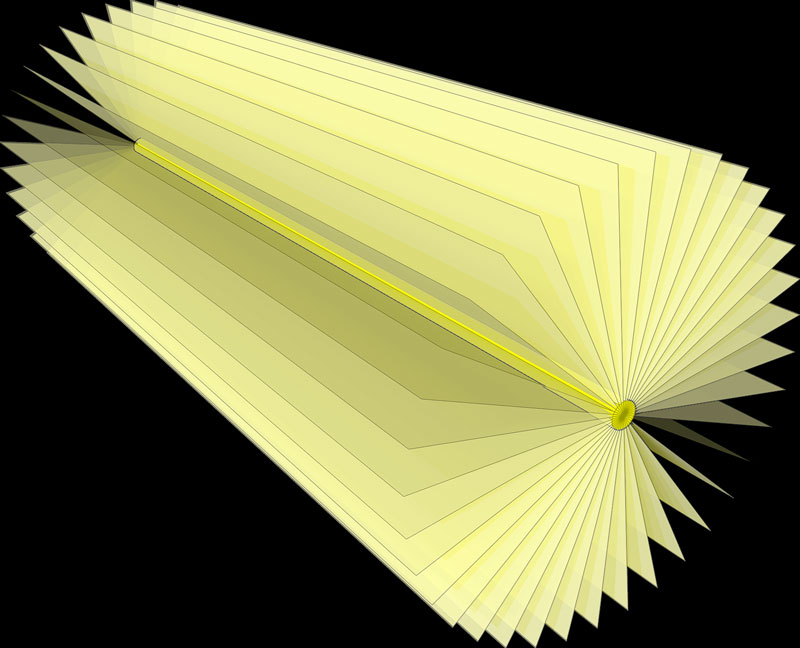
紫色の線はUVrayをモデル化して表現し、水色の面はreflection面(collimatorおよびduct屈折箇所のreflection板)を示します。
このアニメーションでは、reflection面でのreflection率が85%と仮定し、UVrayのenergydensityを彩度として表現しています。
HSBカラーモデル上、direct radiationはH282、S100%、B100%、collimatorによるcollimated lightはS85%、さらに屈曲部のreflection板によるreflection光はS71%として表現しています。
※S0%は完全な白となります。
collimatorを含め、UVrayはreflectionの度にattenuationしていますが、reflectionの回数が少ないため、optical path全体としてgermicideに活用されるrayのenergyは非常に大きいことが分かります。
APPLICATION
Intruduction of constitution/installation instances of UV Long Optical Path Sterilization System
View
(Sorry, translation is underway...)
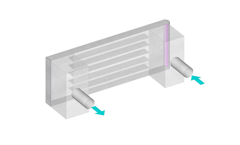
BASIC CONSTITUTION IN STRAIGHT DUCT
Basic constitution housing a unit of a collimator and a UV light source in the middle of the duct.
The unit can be installed wherever accessible in the duct even a gap around the collimator is required for air flow.
APPLICATION FOR AIR CONDITIONING DUCTS
主duct端部の閉止板に近接してcollimatorとUVlight sourceのunitをinstallするconstitution例です。
ほとんどattenuationの無い(reflectionや折り返しの少ない)longなoptical pathを形成することができるため、大きなgermicide effect が期待できます。
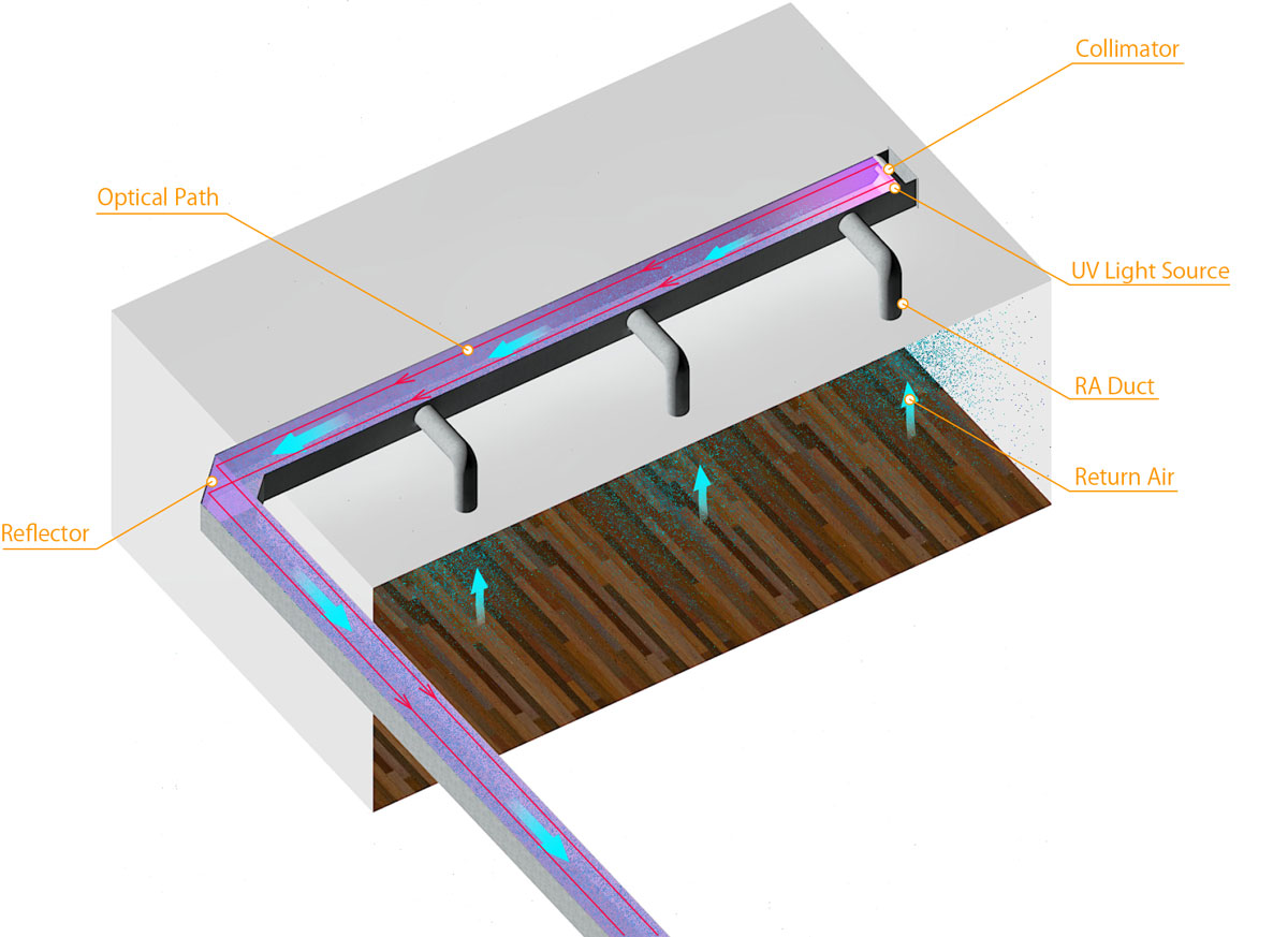
エルボ部分をreflectionunitに置き換えることにより、さらに⾧大なoptical pathを形成することができます。
APPLICATION FOR APPLIANCES
UV Long Optical Path Sterilization Systemを用いたgermicideapplianceのstructureについて、解説します。
line light sourceを用いたシンプルなstructureの例
大きさに制約のあるapplianceをconstitutionする場合、optical path・channelを折り返すstructureとすることにより、コンパクトでありながらlongなoptical pathを実現することができます。
View Details
(Sorry, translation is underway...)
CHANNEL STRUCTURE
airgermicideapplianceは、一般に、コンパクトであることが求められます。また、air清浄機やair conditioningapplianceに内蔵させる場合、当該systemによるgermicideのためのchannelスペースは、大きく制約されてしまいます。このため、airのchannelおよびoptical pathを折り返し、コンパクトにconstitutionするchannelconstitutionの例を示します。
SWITCHBACK AIR CHANNEL
つづら折り状に折り返したchannelに対し、optical pathもreflection板により折り返し追従させることにより、コンパクトでありながら、⾧大なoptical pathをconstitutionすることができます。
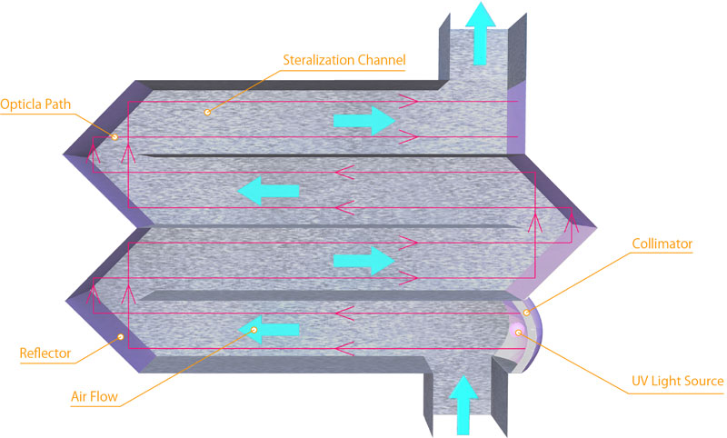
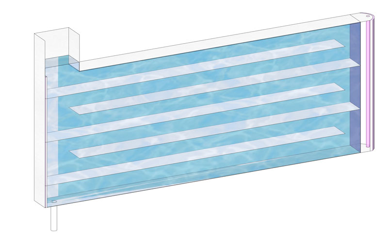
PARALLEL AIR CHANNEL
channelは並列状とすることもできます。冷陰極管によるline light sourceを用い、大きなair flow volumeを処理する場合には、rationalなconstitutionとなります。
処理air flow volumeが一定以上となる場合、平行配置された各channel内の圧力損失(抵抗)が大きく(velocityの2乗に比例)なるため、各channel内のair flow velocityのばらつきが抑制され均等に近づきます。これにより、deviceを通過するairに対するUVのirradiation時間を一定時間以上確保しやすくなります。
平行channelとductは、図のように等圧チャンバーを介して接続することで、さらにair flow velocityの偏りを低減させることができます。
SPIRAL AIR CHANNEL
渦巻き状とすることにより、少ないreflection回数でありながら、⾧大なoptical pathをconstitutionすることができます。
流体のchannel抵抗も抑制することができ、コンパクトで高efficencyなapplianceを実現することができます。
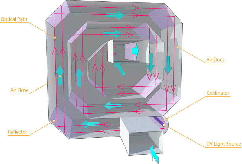
UVは、専用ミラーを用いた場合であってもreflectionを繰り返すとattenuationが大きくなるため、light sourceおよびcollimatorはchannelの外側にinstallし、optical path中、UVrayのenergyの大きな範囲を最大化し、rationalにgermicideされるstructureとしています。
LIQUID GERMICIDAL SYSTEM
「UV Long Optical Path Sterilization System」は、透明度の高いliquidのgermicidedeviceもconstitutionすることができます。
※一定以上の純度の水のgermicideなどにapplicationできますが、水中ではUVのattenuationが大きいため、constitution可能なdeviceの大きさは制限されます。
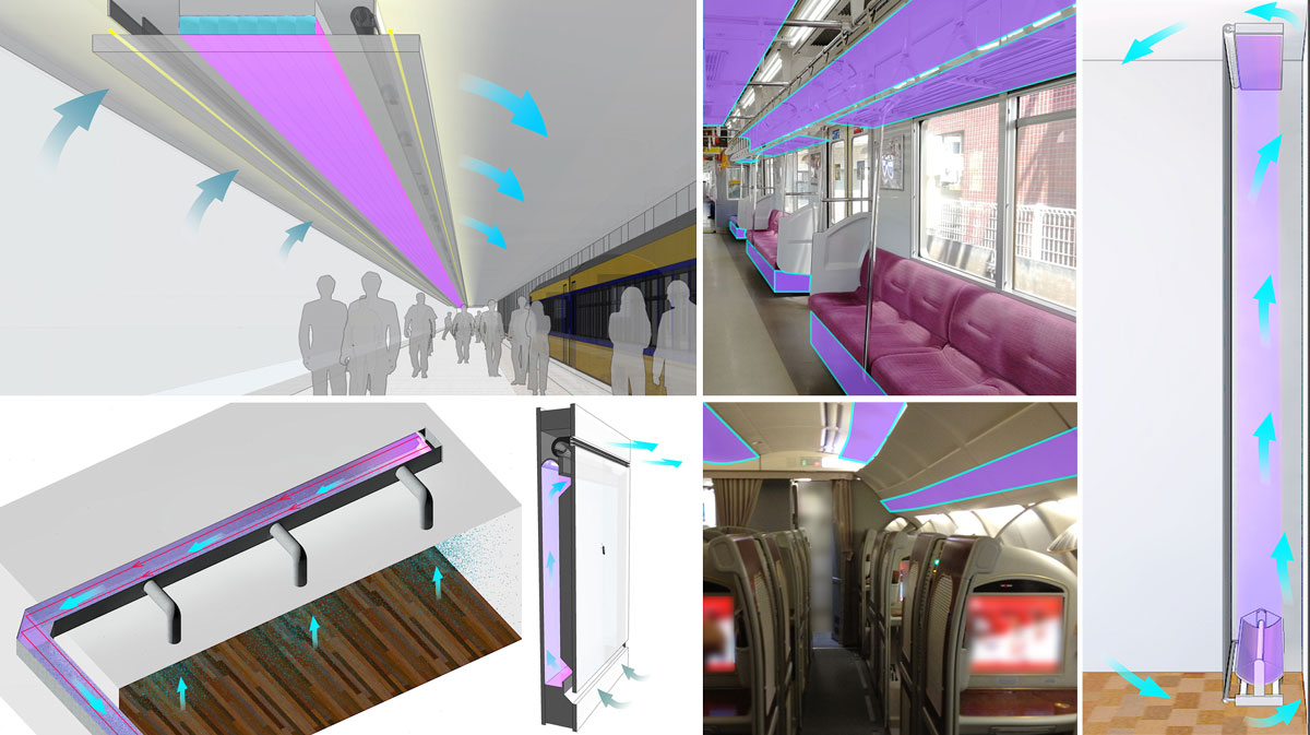
ARCHITECTURAL APPLICATION
indirect lighting等を組み込むなど、意匠的なしつらえとすることも可能な、造作・建築化方法です。
Air-borne infection can be デザインの一部としてconstitutionしつつ、air infectionの防止を図ることができます。
天井へのinstall
折上天井・下がり天井タイプ
折上天井や下がり天井と組み合わせることにより、高意匠かつeffectiveなairgermicidesystemをconstitutionすることができます。
indirect lighting(コーブ照明)やair conditioning制気口(吹出口・吸込口)などを組み込むことで、さらに天井まわりのデザインをすっきりさせることができます。
直線状の折上天井・下がり天井タイプは、公共の通路等、高densityな空間に最適です。
※鉄道駅のプラットフォームなどの場合、自然にairが流通・換気・希釈され、infectionの可能性は低いと考えられますが、airが滞留する、人混みができる時間にはinfectionの可能性が高まるため、このような長optical path germicide systemをconstitutionし、infection preventionを図ることをお薦めします。
また、室内airは対流等により流動を続けるため、必ずしもfanは必要ではありませんが、高densityな公共空間など、より確実なairinfection preventionを図る場合、fanをinstallし、強制的に一定以上のairの循環・germicideを行うconstitutionとすることをお薦めします。
天井チャンバー内活用タイプ
(後日追記予定)
廻縁タイプ
(後日追記予定)
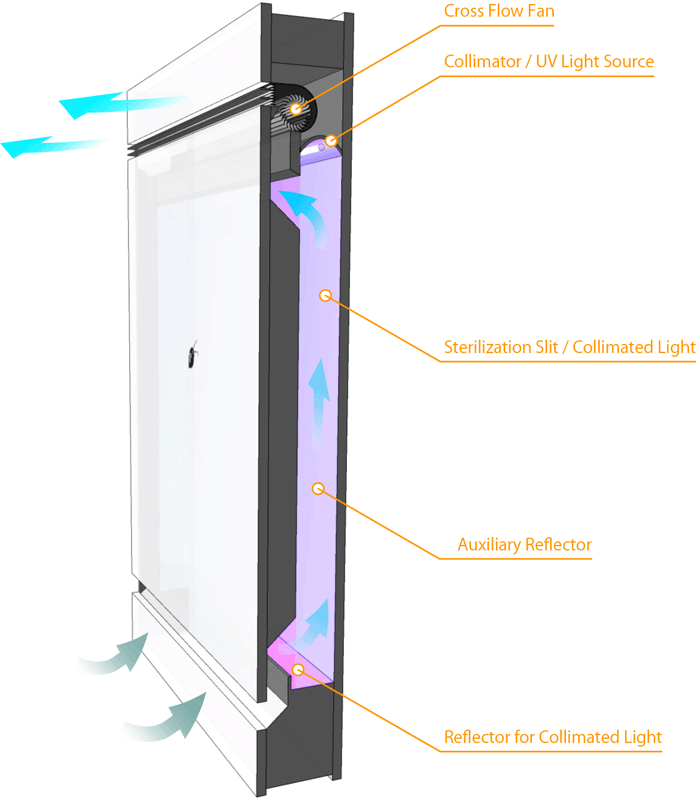
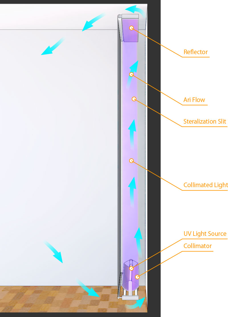
INSTALLATION IN WALLS
ふかし壁面unit
既存の壁面上にairchannelとなるgermicideスリットを追加することにより、長optical pathgermicidesystemを形成することができます。
折上天井・下がり天井タイプ同様、indirect lighting等を組み込むことも可能な、造作・建築化方法です。
デザインの一部としてconstitutionしつつ、airinfectionの防止を図ることができます。
reflection板、目隠し板のinstallにより、reflection・拡散によるUVの漏洩を防止し、人体に安全でありながらも、容易にinstallすることができます。
大部屋や通路等の場合、鉛直方向ではなく、水平方向にUVcollimated lightをirradiationするstructureとし、フカシ壁を水平方向に延長する形状とすると、空間全体をムラ無くeffectiveにgermicideすることができます。
germicide壁面unit~roll screen簡易タイプ
既存の壁面上に、突っ張り棒と遮光roll screenでconstitutionする、とても簡易な長optical pathgermicidesystemです。
installする壁面幅が大きい場合、鉛直方向のポールによりinstallし、側面に目隠し板をinstallします。
重力により正確に上向きにUVcollimated lightを投射するstructureのため、ラフなinstallでも問題なく機能させることができます。
巾木タイプ
(後日追記予定)
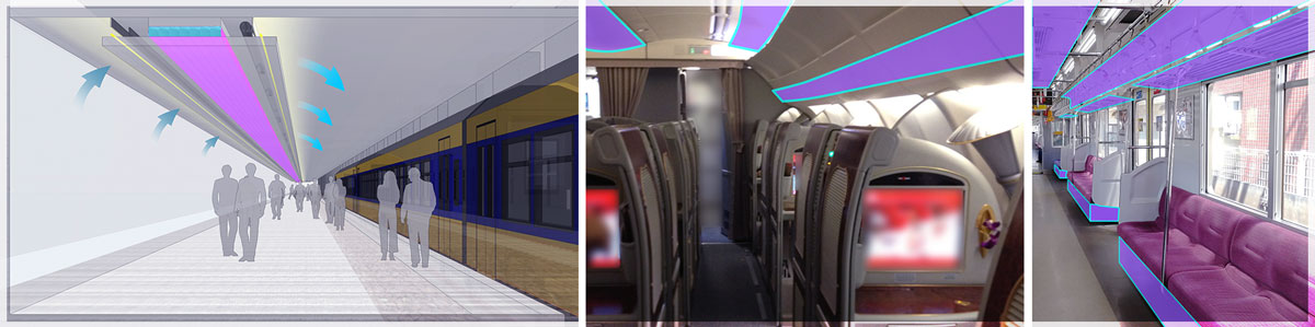
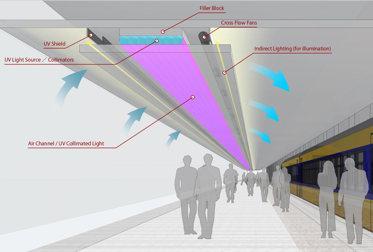
PUBLIC TRANSPORTATION
鉄道車両やバスの車内、航空機内など、公共交通機関の客室内は、airinfectionしやすい高densityな空間となりがちですが、longなdeviceをinstall可能な場合が多く、effectiveなUV Long Optical Path Sterilization Systemを形成することができます。
クロスフローラインfanを用いたstructureとすることにより、空間全体に対し、とりこぼしの少ないgermicideを図ることができます。
上図はbuildingへのinstall例ですが、このconstitutionは鉄道車両や航空機等の室内にも流用することができます。
TRAIN
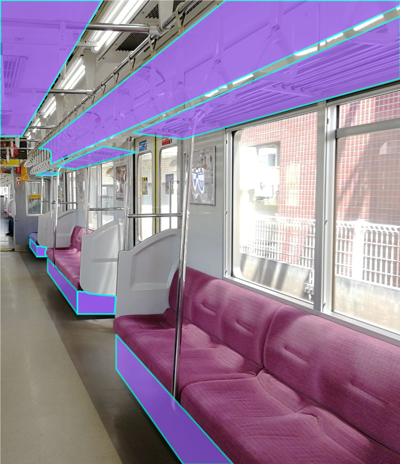
紫色のマーキング箇所は、電車の車内にUV Long Optical Path Sterilization Systemを導入する場合の、installしやすい箇所を示したものです。
車両によりstructure・constitutionは異なりますが、一般に、座席下部、網棚上下、網棚奥の広告スペース、天井面などが、最適なinstall個所と考えられます。
AIRPLANE
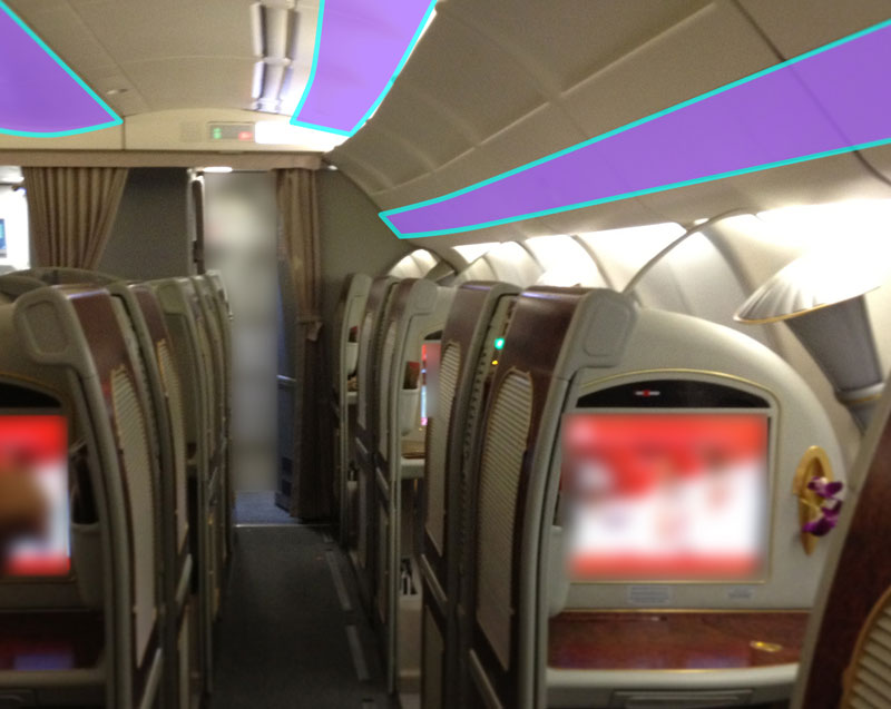
紫色のマーキング箇所は、飛行機の機内にUV Long Optical Path Sterilization Systemを導入する場合の、installしやすい箇所を示したものです。
鉄道車両同様、機体によりstructure・constitutionは異なりますが、荷物入れ・酸素マスク格納スペース・air conditioning設備スペースを除いた天井面にinstallすることが考えられます。
尚、旅客機の場合、一般に、室内airは高性能なHEPAフィルタ―により常時ろ過されており、ウィルスも除去されているものと考えられますが、乗客のdensityに対する、airのろ過air flow volumeは必ずしも十分とは言えないため(ろ過還気系統による室内でのair flow velocityは室内airの対流velocityより小さいと考えられるため)、別系統として、当該systemによる循環germicidesystemを併用することが望ましいと考えます。
その他
上記の他にも、数多くのapplication方法があります。(後日追記予定)
OTHER TECHNICAL NOTES
View
(Sorry, translation is underway...)
EFFECTS FOR HUMAN BODY
germicideに用いるUVは、自然界では地表面に存在しない(到達しない)、UV-Cという、非常に強い破壊力を持つ波長領域のrayを用います。germicideが可能であると同時に、生物の遺伝子を破壊する、危険なrayでもあります。
このため、UV Long Optical Path Sterilization Systemにおいても、人体に有害なrayが、direct radiationはもちろんのこと、間接光・reflection光・拡散光も室内等に漏出して人体にirradiationされないよう、十分注意して計画します。
light sourceのdirect radiationの利用
conventionalのUVgermicidedevice同様、筐体(channel)内面をreflection面とすることで、light sourceから放射されるdirect radiationの、当該reflection面によるreflection光のgermicide effect を付加することができます。
collimatorのfocal pointとlight sourceの大きさ
light sourceは小さいほど、collimatorは大きいほど、light sourceがcollimatorのfocal pointに収束しやすく、はっきりしたcollimated lightを生み出しやすく、effectiveな長optical pathのgermicidesystemをconstitutionすることができます。この意味においては、HIDや高輝度LEDのような、高光度のpoint light sourceの使用が理想的です。対して、冷陰極管のような大きさのあるlight sourceは、一般に単独での出力は大きいものの、collimated lightはぼやけてしまい、長optical pathを形成することが困難となります。
また、collimatorでのreflectionにより得られるcollimated lightは、light sourceおよび基盤等、collimatorの前方に表出する部材に遮られてしまうため、これらがcollimatorの大きさと比較して極力小さくなるようconstitutionします。
※懐中電灯やヘッドライトなどのように、collimator中央部に開口を設け、light sourceは発光部分のみcollimator前方に表出させるstructureとするとrationalです。
point light sourceを用いた場合の effect
point light sourceを用いる場合、放物面の回転体形状のcollimatorを組み合わせることにより、radiant fluxdensityの均一度の高いcollimated lightを生み出すことができます。
尚、point light sourceの場合、通常、背面がソケットや基盤となるため、direct radiationはほとんど活用できない場合があります。
line light sourceを用いた場合の effect
line light sourceを用いる場合、放物線の押出形状のcollimatorを組み合わせることとなりますが、reflectionされるcollimated lightは、板状の立体形状のrayとなります。このとき、当該line light sourceと直交する断面上ではcollimated lightが形成されますが、この板状の立体形状の直交方向から見ると(つまり板状の立体形状の面内では)、direct radiationと同様、各方向に拡散する光となります。このため、line light sourceを用いる場合は、collimated lightとしての性質が弱く、channelと一致させることにより活用できる有効な長さは限定されます。
尚、point light sourceと放物面の回転体形状のcollimatorを組み合わせたものを直線状に連続配置させると、拡散しないlongなcollimated lightを形成することができます。
point light sourceを複数配列してconstitutionするline light source
冷陰極管を用いる場合は、direct radiation・collimatorによるcollimated lightともに活用することができますが、上記の理由およびlight sourceの大きさにより、collimated lightはぼやけてしまい、上記rayによる板状の立体形状の、effectiveにgermicide可能な範囲は、より扁平な(light sourceからのdistanceが短い)形状となります。
このため、冷陰極管の使用は、optical pathおよびchannelとして、扁平な板状の立体形状であるgermicideスリットを内包するdeviceをconstitutionする場合に最適になるものと考えられます。
INQUIRIES
For details on lisencing, consulting and partnership, etc. as to UV Long Optical Path Sterilization System, see MIJINKO FARM.
For other inquiries, contact us from here.